Unpacking Firmware
Firmware images are typically packed and consist of various pieces henceforth called components. In different places, they may be called more specific terms, such as partitions, directories, modules, files, etc.
Many components are containers, which in turn are comprised of other things. As it happens over time, a firmware image for a platform of today may look very different from one meant for a platform from the past. It may be, however, that the target platform cannot be recognized right away, making analysis harder. Such is the case for Intel. We thus need an architecture that is able to distinguish at any given level and allows for extraction.
Partitions
The following diagram is a generic example of a partitioned firmware image with a container that may be of either one or another kind. And in turn, it would contain one or another kind of entries.
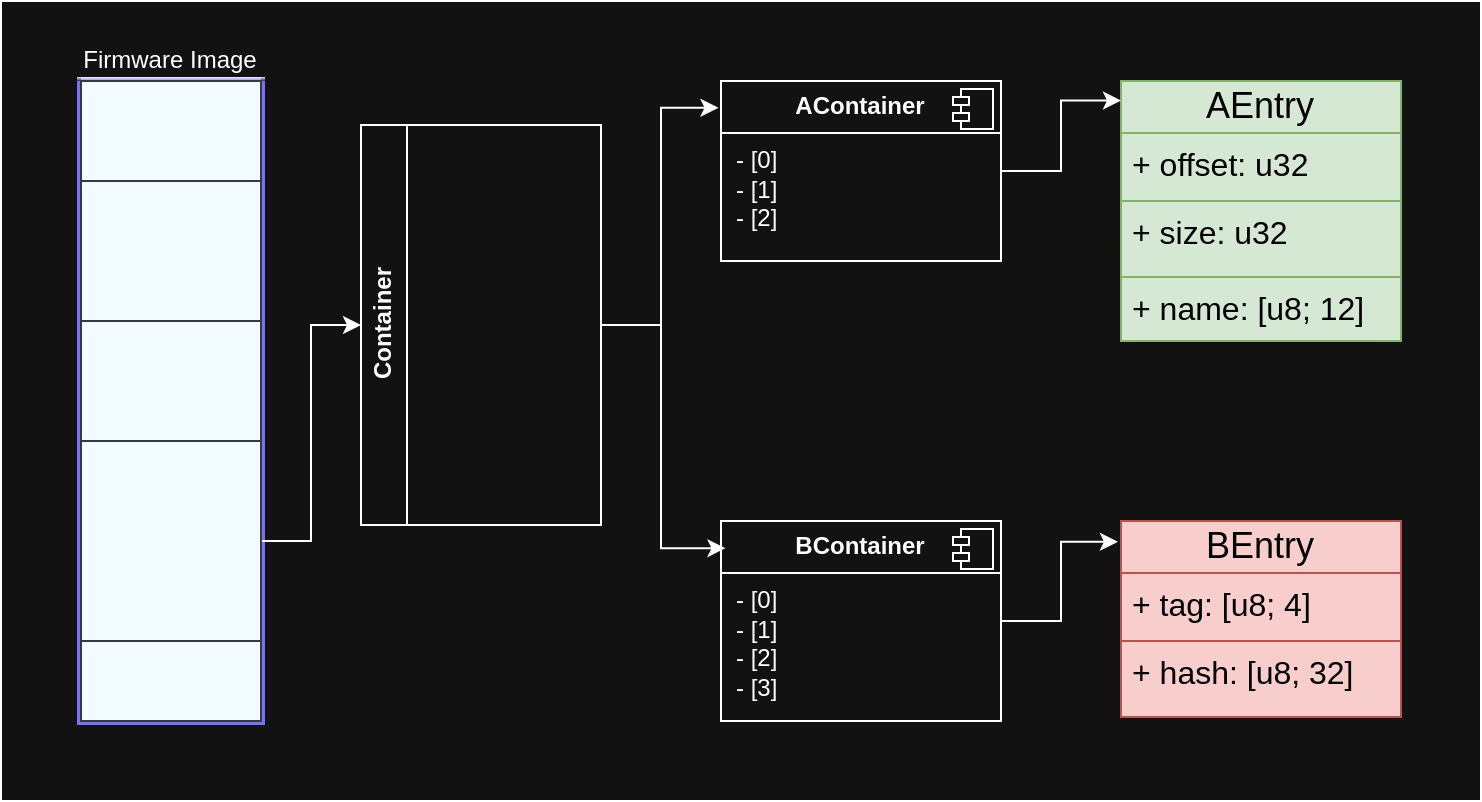
In Rust, we can use enum
types to express this:
enum Container {
    AContainer(Vec<AEntry>),
    BContainer(Vec<BEntry>),
}
Intel ME Generation 2
With the second hardware generation, Intel ME based platforms have introduced
a partitioning scheme called Flash Partition Table (FPT), starting with a $FPT
magic. There are code and data partitions, and the main code partition is called
FTPR.
Code partitions start with a manifest that holds metadata over the modules contained in the partition, as a flat directory. Those modules are in part Huffman-encoded and chunked, and the Huffman tables are part of the mask ROM.
The overall manifest format is header + signature + data. The data part lists the modules with their offsets, sizes and hashes, so that the manifest covers the whole partition’s integrity.
Intel ME Generation 3
With the third hardware generation of Intel ME based platforms, a new operating system was introduced, based on MINIX 3. It needs bootstrapping first, starting with phases called RBE (ROM Boot Extensions) and bup (bringup).
There are multiple kinds of partitions, including Code Partition Directory (CPD) partitions. Those contain executables, their corresponding metadata files, and a manifest that holds a signature over the header before it and its other data. The manifest format with the header and signature is the same as for Gen 2.
The signed data in the manifest includes hashes of the metadata files and other things, so that the manifest suffices to verify the entire CPD’s integrity. Each metadata file contains the counterpart binary’s hash. The binaries themselves are mostly compressed, commonly using LZMA and a few via Huffman encoding.
Knowledge on CPDs, manifests, metadata and binaries can be found in PT Research utilities for unpacking:
Integrated Firmware Image
A variant of ME gen 3 firmware exists based on a different layout, as described in the Atom E3900 series platform enabling guide1:
The IFWI region in SPI flash physically follows the SPI Flash Descriptor Region. It contains all platform firmware components and device firmware components.
The IFWI region is divided into two Logical Boot Partitions, which are identical in size. The Logical Boot Partition layout is defined by the Boot Partition Descriptor Table (BPDT) at the head of the Logical Boot Partition.
There are multiple IFWI data structures, and some do not have a magic to detect, so parsing them is not trivial. ME Analyzer has a lot of logic2 for them. In some cases, the FPT is located right after the IFWI.
The BPDT entries mostly point to CPDs, including the FTPR. Some BPDT entries may point to the FPT.
Samples:
- BPDT v1: Google “Coral” Chromebook
- BPDT v2: System76 Lemur Pro 10 (Tigerlake), Gigabyte Z5903